
Trigger Pulse Generator
The Signalysis Triggered Pulse Generator (TPG) test control system regulates input for non-destructive testing systems ensuring testing control, accuracy and integrity.
Fully integrated into the Signalysis IQC Dinger Test System, the TPG automates, initiates, and controls the hammer sequence. The flexible TPG controller may also be adapted to other non-destructive test applications.
Benefits
- Eliminates subjective testing and inconsistency
- Control and Standardize Test Input
- Ensure Testing Consistency & Accuracy
- Easily Configurable to On-Line Set-Ups
- Pre-Configured to your Specifications
- Full Signalysis Support
HOW IT WORKS
Directs test systems with a precisely-timed 24VDC output pulse with the ability to receive a trigger from:
- The push of a button
- External NO contact
- 24V DC Output
FEATURES
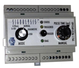
- Select from a variety of input modes including Manual, 4-20mA 0-10V, Diagnostic or USB
- Easy to read LED display
- A variety of input trigger options allows for manual or remote control
Specifications
MODES
Select from one of the following operating modes:
- 4-20mA 0-10V – Allows external device, typically a PLC, to set the pulse time based on either a 4-20mA or 0-10V signal. The 0-10V input’s negative terminal is connected internally to the power supply’s common with a load of 9.4k ohm for 1.2mA max current.
- Manual – Pulse time may be manually set from 0-100msec using the TPG dial.
- Diagnostic – TPG outputs pulses at regular intervals allowing visual LED testing while providing a repetitive output pulse for troubleshooting cabling issues.
- USB – Allows sending commands to TPG to set the pulse time. When connected to a Windows computer with the appropriate hardware drivers loaded, the TPG appears as an RS-232 serial device.
TRIGGERS
The TPG2 supports three different triggers:
- Manual Trigger
- Remote Trigger dry contact – Two TPG terminals for connection of normally open dry contact.
- Remote Trigger 24V – Optically isolated from the power supply, contains two terminals that may be connected to a 24V DC signal for triggering from devices such as a PLC output card.
LEDS
The TPG’s easy to read lighting feature provides quick feedback
- Status – Green light indicates that power is applied and internal program has begun running. Not lit indicates that there is a power issues or the internal program never started. A red light indicates testing in diagnostic mode.
- Triggered – Turns yellow when triggered and stays lit until trigger resets.
- Diagnostic – Used to report diagnostic messages.
POWER SOURCE
The system requires a single 24VDC power supply. The internal control circuit requires a max 100 mA while the output pulse is controlled by a 5A solid state relay and is protected with a 5x20mm, 5A fuse.
OUTPUT
Output duration can range from 0.1 to 100 milliseconds and may be set in multiple ways:
- By a dial on the TPG system
- Proportionally from a 4-20 mA signal
- Proportionally from a 0-10V signal
- Through a command on the serial USB